Science of Fractures
Updated: 29 Jul 2025
Table of Content
- Table of Content
- Fundamentals of Fracture Mechanics
- Methods of Studying Fracture Mechanics
- Scale Mismatch challenge
- Timeline
- References
Fundamentals of Fracture Mechanics
The science of fracture is a field of mechanics to understand and be able to do something before a fracture occur on materials. It focuses on crack initiation and propagation. At its core, it is known as fracture mechanics. [1]
Microscopic cracks and defects are present in all materials due to various sources. When a load is applied to a material, these cracks act as stress concentrators. The stress at the tip of a crack can be significantly higher than the overall applied stress on the material.
Any material has two defining properties, its strength and its toughness. Strength has something to do with its ability to fight back a plastic flow while toughness is its ability to resist a crack propagation.
 fracture in Si at 10K, simulation data from [2]
Types of Fracture:
- ductile fracture: the material undergoes significant plastic deformation before the crack propagates
- brittle fracture: occurs suddenly and with little or no prior plastic deformation
Macroscopic Manifestation of Fracture [6]
- type of loading
- orientation of a crack in relation to its principal stresses
- stability of crack propagation
- magnitude of inelastic deformations
- subcritical crack growth
- crack growth rate
Microscopic Appearances of Fracture [6]
- cleavage fracture
- dimple fracture
- fatigue fracture
- creep fracture
Damage: cavities developed resulting to mechanical properties deterioration [3]
- aspects of damage depends on the type of material and the loading conditions
- phenomological classification of damage:
- brittle damage: nucleation of microvoids or microcracks and their coalescence occuring without plastic deformation
- ductile damage: microvoids develop due to large plastic deformation
- creep damage: micovoids or microcracks nucleate and grow mainly on grain boundaries perpendicular to the tensile stress, or at the grain boundary triple points
- low cycle fatigue
- very low cycle fatigue
- high cycle fatigue damage
- very high cycle fatigue damage
- creep fatigue damage
- spall damage
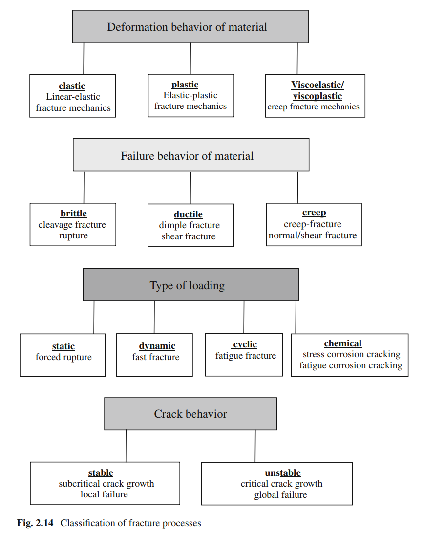
a comprehensive classification list for fracture processes from reference (Meinhard, 2013) in chapter 2.
Modeling Damage
mechanical representation of damage states \(\Rightarrow f(\text{damage variables})\) ?
(covered in detail in chapter 2 from [3]):
- Which effect at the meso-mechanical scale is important when defining damage?
- e.g. development of microscopic voids in creep process
- mathematical property of the damage variable to describe the damage state?
- scalar? vector? tensorial?
- scalar damage variable $\psi(0 \leq \psi \leq 1)$
- vector damage variable $\boldsymbol{\psi} = \psi \textbf{n}$
- second-order damage tensor $\textbf{D}$
- how to quantify damage magnitude?
- e.g. modeling by effective area reduction: $\psi = -A\left(\frac{\sigma}{\psi }\right)^m$, $\sigma$ is the stress, $(A,m)$ are material constants.
damage variables: effective stress, uniaxial state of stress hypothesis of mechanical equivalence between the damaged and the undamaged material other damage variables
Damage mechanics vs. Fracture mechanics from reference (Meinhard, 2013) in chapter 1.
Fracture mechanics provides a relation between geometry ($G$), the position and size ($a$) of the crack-like defect, the external loading ($L$), the local crack loading ($B$), the material resistance against crack propagation ($B_c$), and specific deformation law (elasticity, plasticity, etc.) of the material (M) [6]: \begin{equation} B(G, L, M, a) \leq B_c(M) \end{equation}
Key Concepts
Foundational Principles of Fracture Mechanics: several key theoretical developments that laid the groundwork for modern fracture mechanics that provided the fundamental language and conceptss for analyzing cracked bodies
- first quantitative evidence of stress concentration effects of flaws was provided by Inglis (1913), analyzing elliptical holes in flat plates [13]
- Griffith’s Energy Balance Criterion and Early Insights
- fundamental contradiction: theoretical strength of a material $\neq$ force needed to break atomic bonds e.g. 100MPa $«$ 10,000MPa
- Griffith hypothesized that this discrepancy was due to the presence of microscopic flaws or cracks within the material
- key outcome: the concept of critical energy release rate, $G_c$ representing the energy per unit area required to create a new fracture surfaces, considered as a material property, often referred to as the material’s fracture toughness.
- an existing crack is predicted to propagate if the energy release rate $G$ associated with its extension reaches or exceeds $G_c$
- crack growth occurs when: (energy released from material relaxation) $\geq$ (energy required to create new crack surfaces)
- Linear Elastic Fracture Mechanics (LEFM): stress intensity factor
- LEFM builds upon and extends Griffith’s energy-based concepts by providing a framework to characterize the stress field in the immediate vicinity of a crack tip.
- stress distribution around and close to a crack tip is always the same [5]
- it is predicated on several key assumptions:
- the material is assumed to behave in a linear elastic manner
- plastic deformation is considered to be confined to a very small region around the crack tip relative to the crack length and other characteristic dimensions of the body
- LEFM introduces the stress intensity factor (George R. Irwin, 1957) (SIF), represented by the variable $K$, is a fundamental material property in fracture mechanics that describes the “stress state at a crack tip, related to the rate of crack growth, and is used to establish failure criteria due to fracture”
- SIF value $K$ depends on the applied external load $\sigma$, the size and geometry of the crack $a$, and the geometry of the body containing the crack $f(a/W)$: \begin{equation} K = \sigma \sqrt{\pi a} f(a/W) \label{eq:sif} \end{equation}
- LEFM builds upon and extends Griffith’s energy-based concepts by providing a framework to characterize the stress field in the immediate vicinity of a crack tip.
- Modes of Fracture: the way a crack grows is categorized into 3 distinct modes of displacement, which describes the relative movement of the crack surfaces:
- mode I (opening mode): crack faces are pulled directly apart under a tensile stress that is perpendicular to the crack plane
- mode II (sliding mode): crack surfaces slide over each other in a direction perpendicular to the leading edge of the crack. this is caused by an in-plane shear stress
- mode III (tearing mode): crack surfaces move relative to each other in a direction parallel to the leading edge of the crack, caused by an out-of-plane shear stress
- Stress intensity factor and fracture toughness can be defined for each mode ($K_I, K_{II}, K_{III}$) and \(K_{Ic}, K_{IIc}, K_{IIIc}\)
- will equation \eqref{eq:sif} change for each mode?
Key Concepts in Fracture Mechanics Some key concepts from this field are:
- stress intensity factor $K_I$, fracture toughness $K_{IC}$
- $K_I$: this parameter quantifies the magnitude of the stress field at a crack tip, a function of applied stress, the size and geometry of the crack and the geometry of the component.
- $K_{IC}$: an intrinsic property of a material that represents its resistance to crack propagation
- fundamental principle of fracture mechanics is that failure will occur when the stress intensity factor reaches the material’s fracture toughness. \begin{equation}K_I \ge K_{IC}\end{equation}
- energy release rate $G$ and toughness $G_C$
- crack tip radius
- stress fields and the process zone
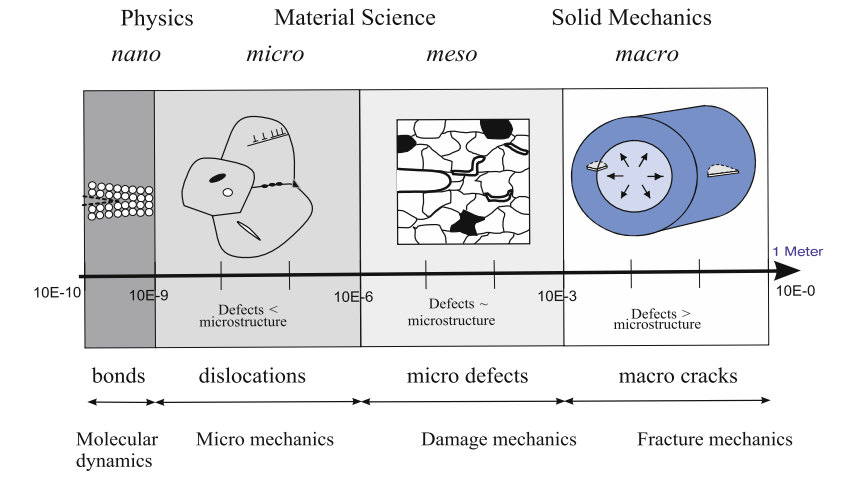
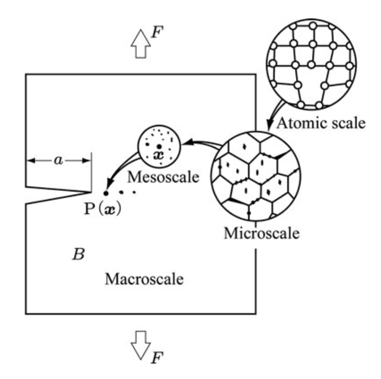
Fracture Phenomena by Length Scale: understanding and modeling fracture effectively requires a clear acknowledgement of its hierarchical nature. The physical mechanisms that dominate fracture processes, the relevant material features, and consequently the most appropriate modeling approaches, vary significantly with the length scale under consideration.
Fracture at different length scale (Murakami, 2012)
- Nanoscale fracture ($<100$ nm): fracture is governed by the discrete interactions between individual atoms and molecules
- key phenomena at this scale include the explicit breaking of atomic bonds at a crack tip, the nucleation and motion of dislocations from highly stressed regions near a crack,
- modeling tools:
- molecular dynamics (MD)
- DFT (for higher accuracy) and other quantum mechanical methods if electronic effects in bond breaking is important
- Mechanism of damage: tensile decohesion or shear decohesion [3]
- Microscale fracture (100nm-100$\mu$m)
- key features at this scale include grain boundaries in polycrystalline materials, interfaces between different phases in multi-phase materials, the presence of inclusions or precipitates, microscopic voids, and the formation and interaction of microcracks.
- modeling tools:
- continuum mechanics formulation (e.g., crsytal plasticity finite element methods (CPFEM))
- cohesive finite element modeling, cohesive zone models (CZMs)
- phase-field models to captura crack propagation through heterogeneous microstructures
- Mechanism of damage:
- cleavage
- growth and coalescence of microvoids
- glide plane decohesion
- void growth due to grain-boundary diffusion
- Mesoscale fracture (100$\mu$m - few mm\cm)
- bridges the gap between detailed microscopic behavior and macroscopic continuum response
- this scale often involve the collective behavior of multiple microcracks, the accumulation of distributed damage, and the localization of this damage into larger, more distinct crack bands.
- concept of a Representative Volume Element (RVE) becomes critically important at the mesoscale. An RVE is a notional volume of material that is large enough to be statistically representative of the heterogeneous microstructure, yet small enough to be considered a material point in a macroscopic continuum model. The properties derived from RVE analyses are then used to inform the constitutive behavior at the macroscale.
- modeling tools:
- Continuum Damage Mechanics (CDM)
- advanced finite element method (FEM) simulations incorporating sophisticated damage models or explicit mesostrctural features
- phase-field models
- lattice models
- Macroscale fracture (>few mm/cm)
- deals with the mechanical response of bulk materials and entire engineering structures or components
- cracks are typically treated as distinct geometric discontinuities rather than diffuse damage zones (though CDM can also be applied at this scale with homogenized damage properties)
- primary focus of macroscale fracture modeling is on assessing structural integrity, determining crack stability (i.e., whether an existing crack will propagate under given loads), predicting the remaining service life of cracked components, and understanding fatigue crack growth behavior.
- modeling tools:
- Linear Elastic Fracture Mechanics (LEFM)
- Elastic-Plastic Fracture Mechanics (EPFM)
- Finite Element Method (FEM) is extensively employed, often with specialized techniques to represent cracks, such as discrete crack elements, cohesive zone elements along potential crack paths
- advanced methods like the Extended Finite Element Method (XFEM)
- Peridynamics, particularly suited for large-scale simulations involving dynamic fracture and fragmentation
Methods of Studying Fracture Mechanics
Linear Elastic Fracture Mechanics (LEFM)
- built upon the principles of linear elasticity and an energy-based criterion for crack propagation, making it highly effective for analyzing brittle materials or ductile materials under conditions where plastic deformation is minimal.
- crack problems are analyzed in bodies whose deformation behavior can be assumed to be linear-elastic according to the generalized Hooke’s law [6]
- in most cases: non-linear effects are limited to small areas which may be neglected in comparison to crack size or the component dimensions
- elastic material are isotropic, but may be anisotropic.
- the linearity implies small displacements and infinitesimal deformations
- The entire theoretical structure of LEFM rests upon a single, crucial assumption: small-scale yielding (SSY).
- in SSY, the plastic zone is situated inside the elastic crack tip
Elastic-Plastic Fracture Mechanics (EPFM)
- also designated as ductile fracture mechanics
- plastic deformation is associated with a significant amount of energy dissipation in the body, which can get rather larger compared to the energy consumption during crack propagation [6]
- analytical solution methods of elastic-plastic fracture mechanics are very limited and restricted to simple material models, plane crack configurations and mostly monotonic loads. [6]
Finite Element Method (FEM)
- often used interchangeably with Finite Element Analysis (FEA), is the most widely established and versatile numerical technique for solving problems in structural mechanics. It has become the workhorse for stress analysis and has been adapted to provide powerful tools for fracture mechanics calculations. [7]
- FEM is a numerical procedure for obtaining approximate solutions to the partial differential equations that govern physical phenomena [6]
- in solid mechanics, the method works by taking a complex geometric domain and discretizing it into a collection, or “mesh,” of smaller, simpler, interconnected subdomains called finite elements. Common element shapes include triangles and quadrilaterals in 2D, and tetrahedra and hexahedra (bricks) in 3D.
- the power of FEM lies in its ability to model virtually any geometry and loading condition with an accuracy acceptable to engineers,
Extended Finite Element Method (XFEM)
- It was conceived with the specific goal of overcoming the most significant practical limitation of the traditional Finite Element Method in this domain: the strict requirement that the finite element mesh must conform to the crack geometry, and the associated need for cumbersome remeshing during crack propagation simulations
- XFEM is built upon a powerful mathematical concept known as the Partition of Unity Method (PUM). The standard FEM approximation represents the solution as a sum of polynomial shape functions, each multiplied by a nodal value.
- eXtended Finite Element Method (XFEM) handles geometries containing singularities without the need of building a conforming mesh [7], [8], [9]
Peridynamics
- introduced by Stewart Silling at Sandia National Laboratories in 2000 [11]
- all of the preceding methodologies, LEFM, EPFM, FEM, and XFEM, are “local” theories rooted in classical continuum mechanics (CCM).
- governing equations are partial differential equations that rely on spatial derivatives of the displacement field (to define strain) and the stress field (in the equations of equilibrium).
- At a discontinuity such as a crack surface, the displacement field is no longer continuous, and its derivatives are mathematically undefined.
- this is the fundamental source of the stress singularity problem that requires the specialized treatment seen in LEFM (the K-field), FEM (quarter-point elements), and XFEM (singular enrichments).
- Peridynamics (PD) sidesteps this entire issue by reformulating the equations of motion in a non-local, integral form. It dispenses with the concepts of stress and strain tensors and their spatial derivatives.
- fracture is not governed by an external rule; it is an emergent phenomenon that arises naturally from the material’s own constitutive law.
- achieved by incorporating a failure criterion at the most fundamental level: the individual bond. A simple and common constitutive model for a bond is to assume it behaves like a spring up to a certain critical stretch, $s_c$. If the stretch of a bond between two points exceeds this critical value, the bond is considered irreversibly “broken” and can no longer sustain a force. [12]
- this approach represents a fundamental shift in how fracture is modeled. In FEM and XFEM, the complexity of fracture is handled by the numerical solver, which must employ special techniques (remeshing, enrichment) and be guided by an external failure law. Peridynamics shifts this complexity from the solver to the constitutive model.
Scale Mismatch challenge
A significant hurdle in comprehensive fracture analysis is the “scale-mismatch” challenge. Phenomena that are critical at a lower scale (e.g., the diffusion of hydrogen atoms at the nanoscale, or the interaction of dislocations with precipitates at the microscale) can have profound and often detrimental consequences at a higher scale (e.g., hydrogen embrittlement leading to macroscopic failure, or the initiation of fatigue cracks). However, directly simulating these processes across the entire range of scales—from atomic interactions to component failure—is typically computationally prohibitive.
Molecular dynamics simulations, for example, are powerful for elucidating atomistic mechanisms but are severely limited in the time and length scales they can practically address. One way to overcome this, with the current advent of GPUs, is to use an computationally efficient force field that would allow large scale and long range simulations. Conversely, macroscale models often rely on phenomenological constitutive laws that might not accurately capture the underlying physics if they are not properly informed by an understanding of lower-scale behaviors. This scale mismatch necessitates the development of robust multiscale modeling strategies or the formulation of advanced, physics-informed macroscale models that can effectively encapsulate the critical effects of lower-scale phenomena without requiring their explicit resolution.
Timeline
References
- https://ocw.tudelft.nl/wp-content/uploads/Materiaalkunde_1_slides_chapter8.pdf
- https://zenodo.org/records/1747215
- Murakami, S. (2012). Continuum damage mechanics: a continuum mechanics approach to the analysis of damage and fracture (Vol. 185). Springer Science & Business Media.
- Irwin, G. R. (1957). Analysis of stresses and strains near the end of a crack traversing a plate.
- Janssen, M., Zuidema, J., & Wanhill, R. (2024). Fracture Mechanics: An Engineering Primer. TU Delft OPEN Books.
- Meinhard, K. (2013). Finite elements in fracture mechanics: Theory–Numerics–Applications Dordrecht.
- Lard II, G., & Epstein, J. S. (1992). Fracture mechanics and finite element analysis. Mechanical Engineering, 114(11), 69.
- Duflot, M., Wyart, E., & Lani, F. (2007). Application of the eXtended Finite Element Method (XFEM) in industrial damage tolerant approaches for aerospace structures.
- Moës, N., Dolbow, J., & Belytschko, T. (1999). A finite element method for crack growth without remeshing. International journal for numerical methods in engineering, 46(1), 131-150.
- Belytschko, T., & Black, T. (1999). Elastic crack growth in finite elements with minimal remeshing. International journal for numerical methods in engineering, 45(5), 601-620.
- Silling, S. A. (2000). Reformulation of elasticity theory for discontinuities and long-range forces. Journal of the Mechanics and Physics of Solids, 48(1), 175-209.
- Pagani, A., Enea, M., & Carrera, E. (2022). Quasi‐static fracture analysis by coupled three‐dimensional peridynamics and high order one‐dimensional finite elements based on local elasticity. International Journal for Numerical Methods in Engineering, 123(4), 1098-1113.
- CE, Inglis (1913). Stresses in a plate due to the presence of cracks and sharp corners. Trans Inst Naval Archit, 55, 219-241.